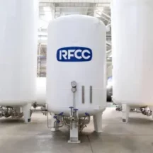
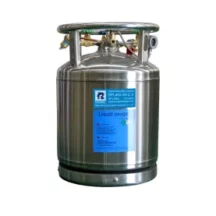
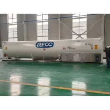
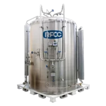
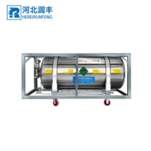
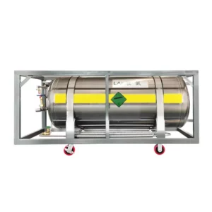
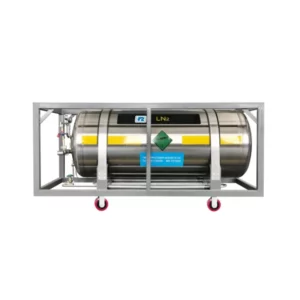
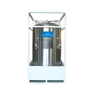
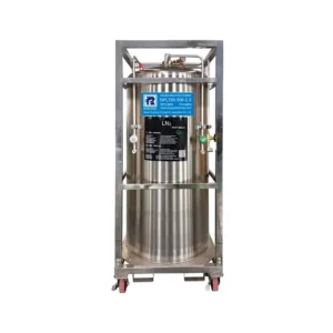
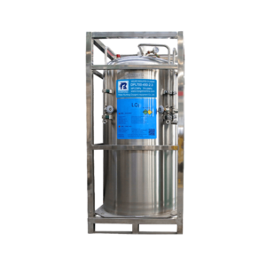
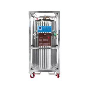
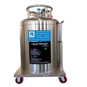
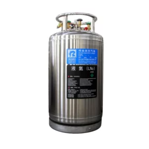
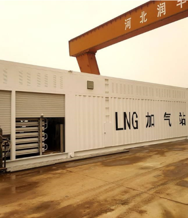
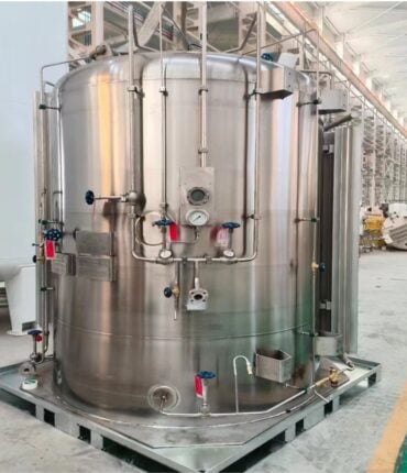
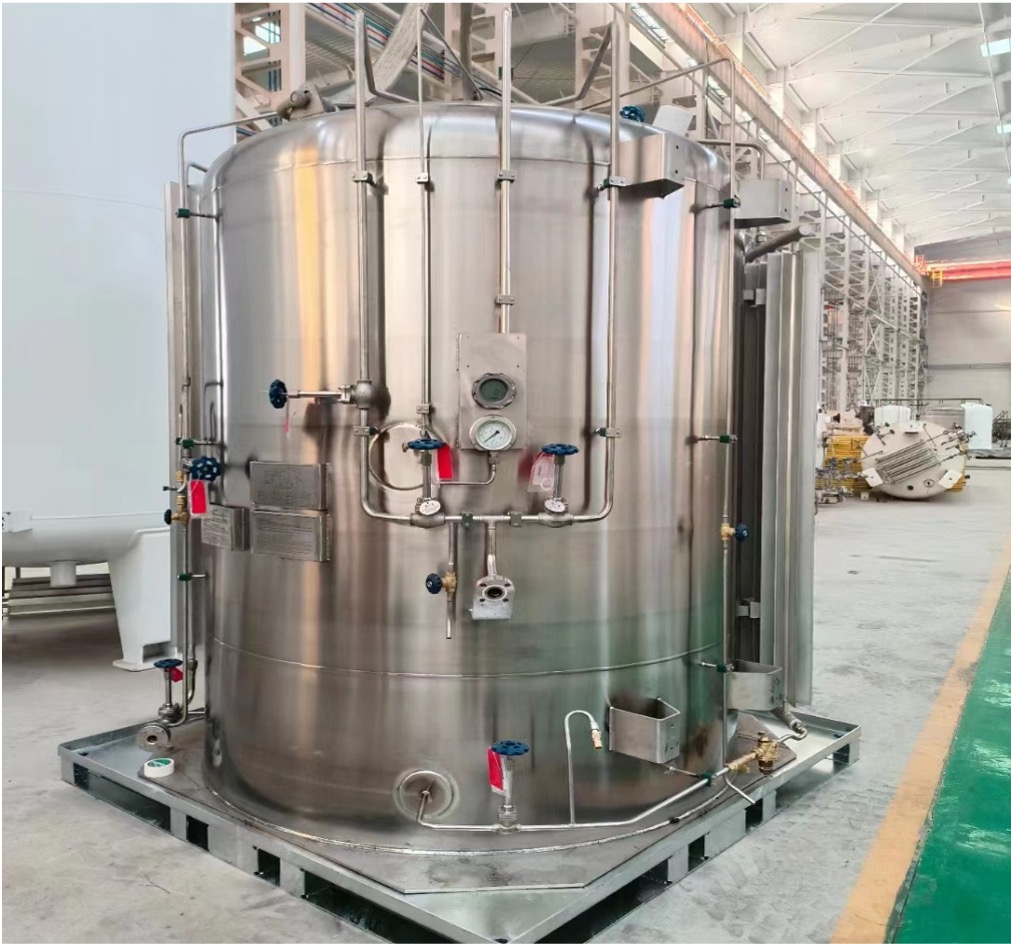
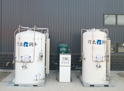
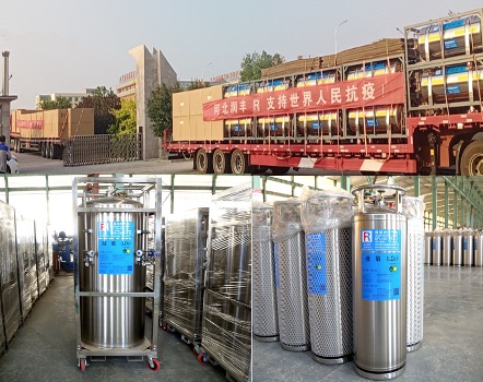
Are used for the efficient,safe and long-term storage of cryogenic
liquefied gases(liquid nitrogen,oxygen or argon)
thanks to their double-walled,vacuum-Perlite insulated design.
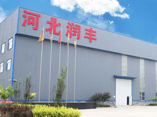
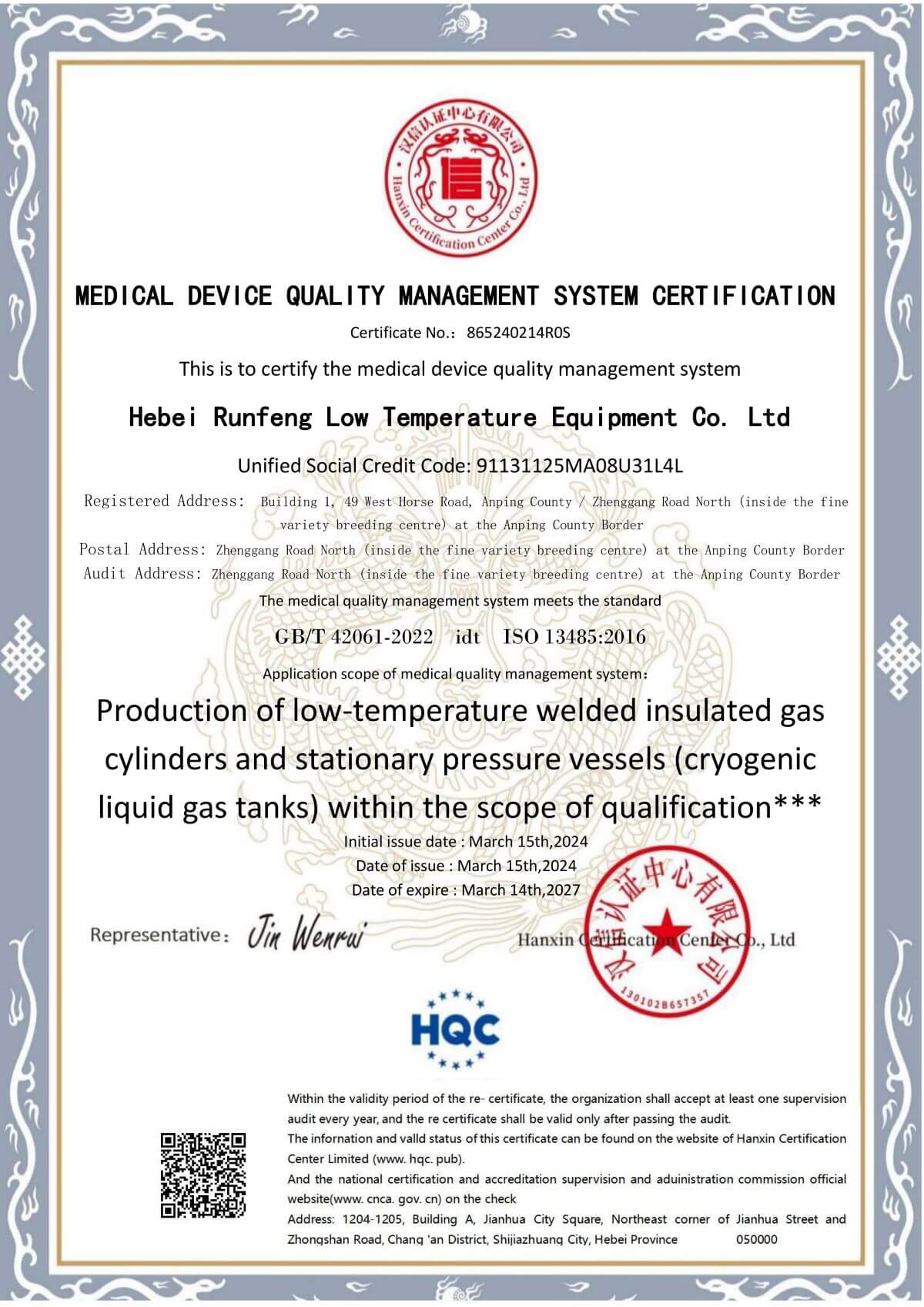
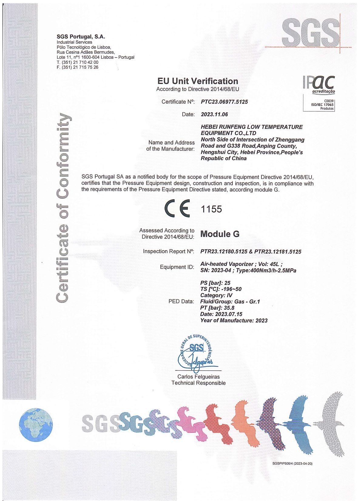
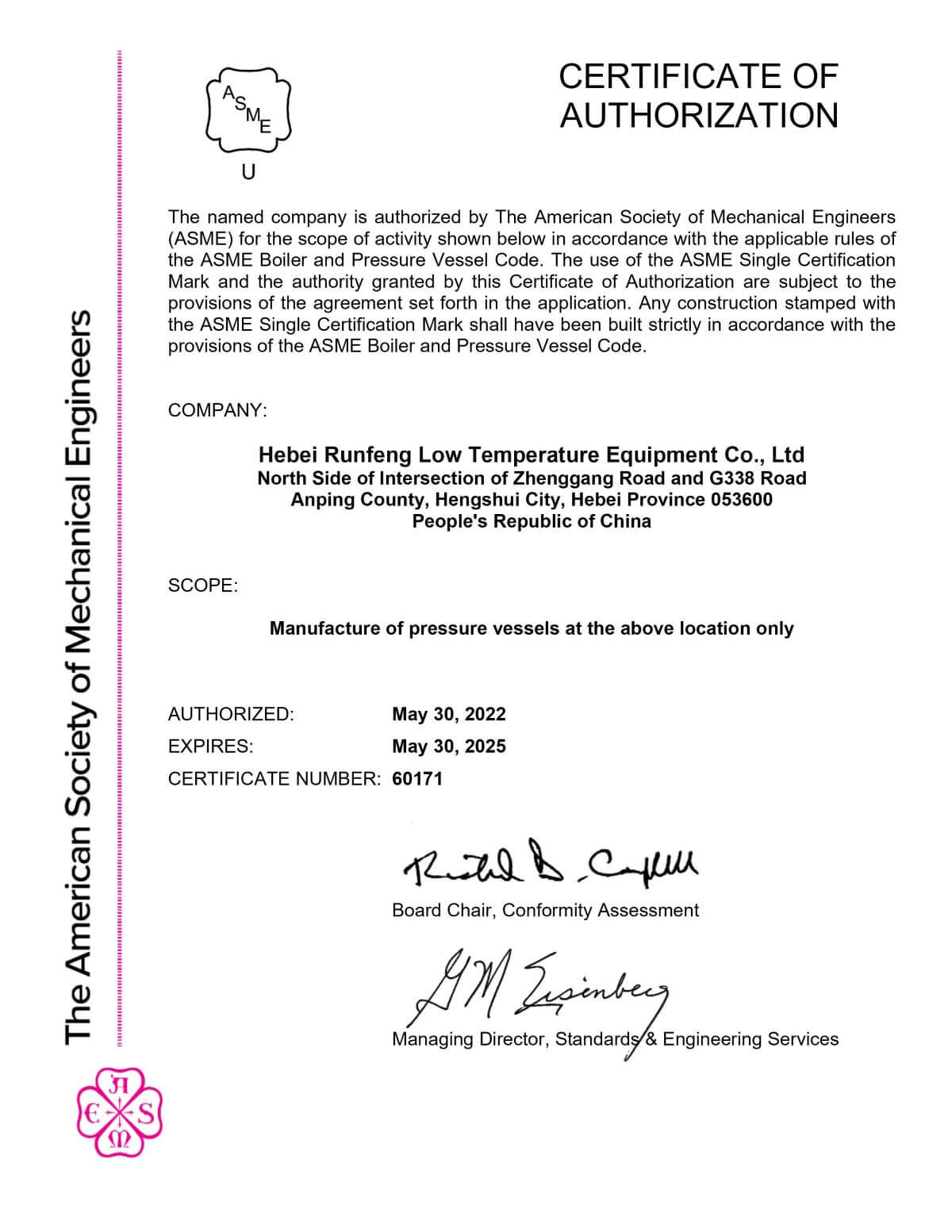
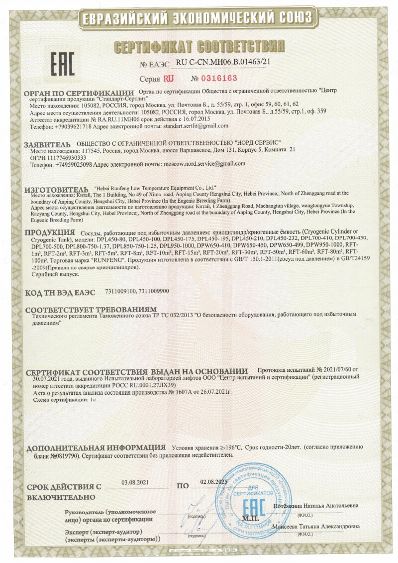
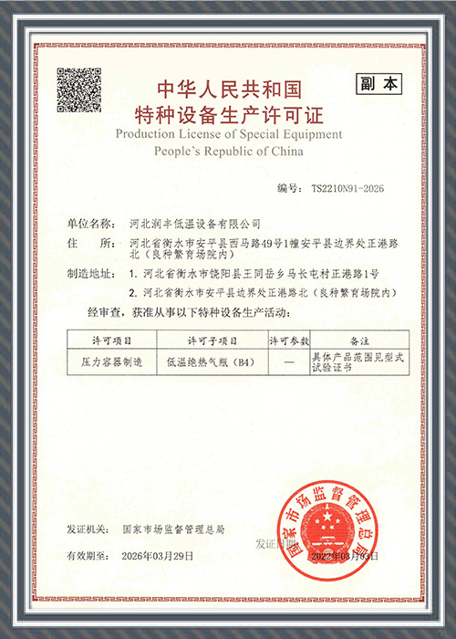
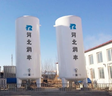
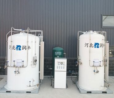
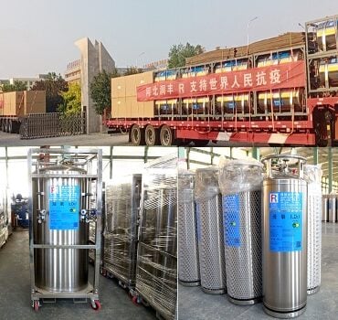
RFCC (RunFeng Cryogenic China) is a leading provider of cryogenic pressure vessel solutions, established in 2005, specializing in design, manufacturing, and R&D. The company boasts strong production capabilities, with a 20,000 sqm Dewar bottle production workshop and a 50,000 sqm large-scale cryogenic storage tank plant. It has an annual production capacity of 30,000 Dewar cylinders and 2,000 cryogenic tanks. RFCC holds 25 patents and has earned multiple international certifications, including ISO9001, ASME, and EU-CE.
